ロボットアーム
レンダリング結果
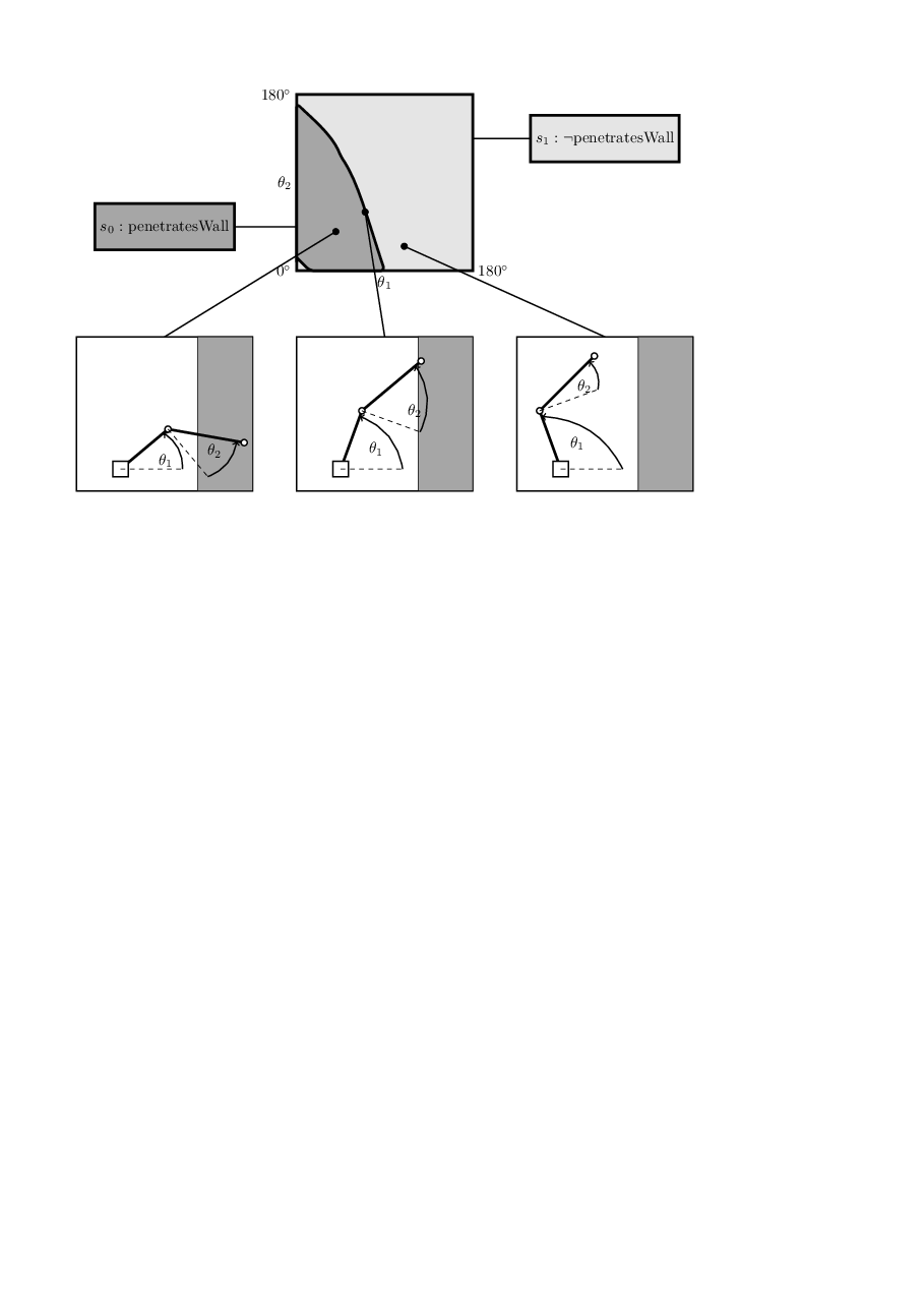
TeXソース
TeXソース
入力コード
\documentclass{tetsujsarticle}
\usepackage{tetsuryoku}

\begin{document}

\newdimen\xbase
\newdimen\ybase
\def\endDom{4}
\begin{tikzpicture}[domain=0:4]
  \def\ColSymBorder{black}
  \def\ColSymBorderTwo{black}
  \def\ColSymFill{gray!70}
  \def\ColSymFillTwo{gray!20}
  \def\wallColor{gray!70}
  \tikzstyle{block} = [draw, color=\ColSymBorder, ultra thick, fill=\ColSymFill, rectangle,  minimum height=3em, minimum width=6em];
  \draw[color=\ColSymBorderTwo, ultra thick, fill=\ColSymFillTwo] (0,0) rectangle (4,4);
  \draw (0,0) node[below,left]{$0^\circ$} -- (4,0) node[below,midway] {$\theta_1$} node[below,right] {$180^\circ$};
  \draw (0,0) -- (0,4) node[left,midway] {$\theta_2$} node[left] {$180^\circ$};

  \def\wallOffset{50pt}
  \def\marginOff{5pt}


  \draw[ultra thick,color=\ColSymBorder,fill=\ColSymFill, rounded corners=3pt]
                   (0,0.2) .. controls (0,1) and (0,2) ..   (0,3.8)
                         .. controls (0.3,3.5) and (0.8,3.1) .. (1,2.6)
                         .. controls (1.4,2.0) and (1.6,1.2) .. (2,0)
                         .. controls (1,0) and (0.5,0) .. (0.3,0)
                         .. controls (0.2,0.1) and (0.1,0.2) .. (0,0.3);
                         %.. controls (3,0) and (2,0) .. (0,0);

  \newcounter{i}
  \setcounter{i}{0}
  \foreach \x in {1,100,...,180}{
   \foreach \y in {1,100,...,180}{
     %\ifthenelse{ {cos(\x)*40+50/cos(90-(\x+\y))} < 50}
     %\ifthenelse{ \lengthtest{ {\f{\x}} pt < 50 pt}}

       \pgfmathparse{ (
       (cos(\x)*40pt+sin(\x+\y)*50pt)<(\wallOffset+\marginOff)) &&
       (cos(\x)*40pt+sin(\x+\y)*50pt)>(\wallOffset-\marginOff))) ?1:0}
       \ifnum\pgfmathresult>0
          %penetrates the wall
          \stepcounter{i}
       \else
          %out of the wall
       \fi


   }
  }

  \draw[thick,color=\ColSymBorder] (-2,1) -- (0,1);
  \node[block] at (-3,1) {$s_0: $ penetratesWall};
  \draw[thick,color=\ColSymBorderTwo] (6,3) -- (4,3);
  \node[draw, color=\ColSymBorderTwo, ultra thick, fill=\ColSymFillTwo, rectangle,
  minimum height=3em, minimum width=6em] at (7,3) {$s_1: \neg$penetratesWall};

  %%%%%%%% PAINTING THE ROBOT STARTS HERE:

  \newcommand*{\Robot}[4]{
    %%%%%%%%%%%%%%%%%%%%%%%%%%%%%%%%%%%%%%%%%%%%%%%%%%%%%%%%%%%%%%%%%%%%%%%%%
    \pgfmathsetlengthmacro{\rone}{40pt} %length link1
    \pgfmathsetlengthmacro{\rtwo}{50pt} %length link2
    \pgfmathsetlengthmacro{\rw}{10} %width of base rectangle
    \pgfmathsetlengthmacro{\thetaone}{#1} %angle base-link1
    \pgfmathsetlengthmacro{\thetatwo}{#2} %angle link1-link2
    \coordinate (base) at (#3,#4); %base coordinates

    %\coordinage (cspace) at ({#1/180*\endDom},{#2/180*\endDom})

    \path (base);
    \pgfgetlastxy{\xbase}{\ybase};
    \draw[thick,color=black] ({\xbase+1cm},{\ybase+3.0cm}) -- ({#1/180*\endDom},{#2/180*\endDom});
    \draw[fill=black] ({#1/180*\endDom},{#2/180*\endDom}) circle (2pt);


    \draw[thick,color=black] ({\xbase-1cm},{\ybase-0.5cm}) rectangle
    ({\xbase+3cm},{\ybase+3cm});

    \draw[fill=\wallColor] ({\xbase+\wallOffset}, {\ybase-0.5cm}) rectangle
    ({\xbase+3cm}, {\ybase+3cm});

    \pgfmathsetlengthmacro{\tx}{\rone*cos(\thetaone)+\xbase}
    \pgfmathsetlengthmacro{\ty}{\rone*sin(\thetaone)+\ybase}
    \coordinate (t1) at (\tx,\ty);

    \pgfmathsetlengthmacro{\sx}{\rtwo*sin(\thetaone+\thetatwo)+\tx}
    \pgfmathsetlengthmacro{\sy}{-\rtwo*cos(\thetaone+\thetatwo)+\ty}
    \coordinate (t2) at (\sx,\sy);
    \draw[ultra thick,black] (base) -- (t1);% node[below] {$\tx \ybase \xbase \ty$};
    \draw[ultra thick,black] (t1) -- (t2);% node[below] {$\tx \ybase \xbase \ty$};

    \draw[thick,color=black,fill=white!30] ({\xbase-0.5*\rw},{\ybase-0.5*\rw}) rectangle++ (\rw,\rw);
    \draw[thick,color=black,fill=white!10] (t1) circle (2pt);
    \draw[thick,color=black,fill=white!10] (t2) circle (2pt);


    %% dashed line to represent link two at 0 degree
    \pgfmathsetlengthmacro{\rtmp}{\rone }
    \pgfmathsetlengthmacro{\tmpx}{\rtmp*sin(\thetaone)+\tx}
    \pgfmathsetlengthmacro{\tmpy}{-\rtmp*cos(\thetaone)+\ty}
    \coordinate (tmp1) at (\tmpx,\tmpy);
    \draw[dashed,color=black] (t1) -- (tmp1);

    %% dashed line to represent link one at 0 degree
    \pgfmathsetlengthmacro{\tmpx}{\rone+\xbase}
    \pgfmathsetlengthmacro{\tmpy}{\ybase}
    \coordinate (tmp0) at (\tmpx,\tmpy);
    \draw[dashed,color=black] (base) -- (tmp0);


    \pgfmathsetlengthmacro{\tmpx}{\rone+\xbase}
    \pgfmathsetlengthmacro{\tmpy}{\ybase}

    \pgfmathsetlengthmacro{\tmpx}{0.9*\rone*cos(\thetaone)+\xbase}
    \pgfmathsetlengthmacro{\tmpy}{0.9*\rone*sin(\thetaone)+\ybase}
    \coordinate (tmp0t) at (\tmpx,\tmpy);

    \pgfmathsetlengthmacro{\tmpx}{0.9*\rtwo*sin(\thetaone+\thetatwo)+\tx}
    \pgfmathsetlengthmacro{\tmpy}{-0.9*\rtwo*cos(\thetaone+\thetatwo)+\ty}
    \coordinate (tmp1t) at (\tmpx,\tmpy);

    % ($(O)+(\StartAngle:-\Radius)$) is the center of the yellow circle

    \draw[bend right,thick,->]  (tmp1) to node [auto] {$\theta_2$} (tmp1t);
    \draw[bend right,thick,->]  (tmp0) to node [auto] {$\theta_1$} (tmp0t);
    %%%%%%%%%%%%%%%%%%%%%%%%%%%%%%%%%%%%%%%%%%%%%%%%%%%%%%%%%%%%%%%%%%%%%%%%%
  }


  \Robot{40}{40}{-4}{-4.5}
  \Robot{70}{60}{1}{-4.5}
  \Robot{110}{25}{6}{-4.5}
\end{tikzpicture}


\end{document}