サンプル2
レンダリング結果
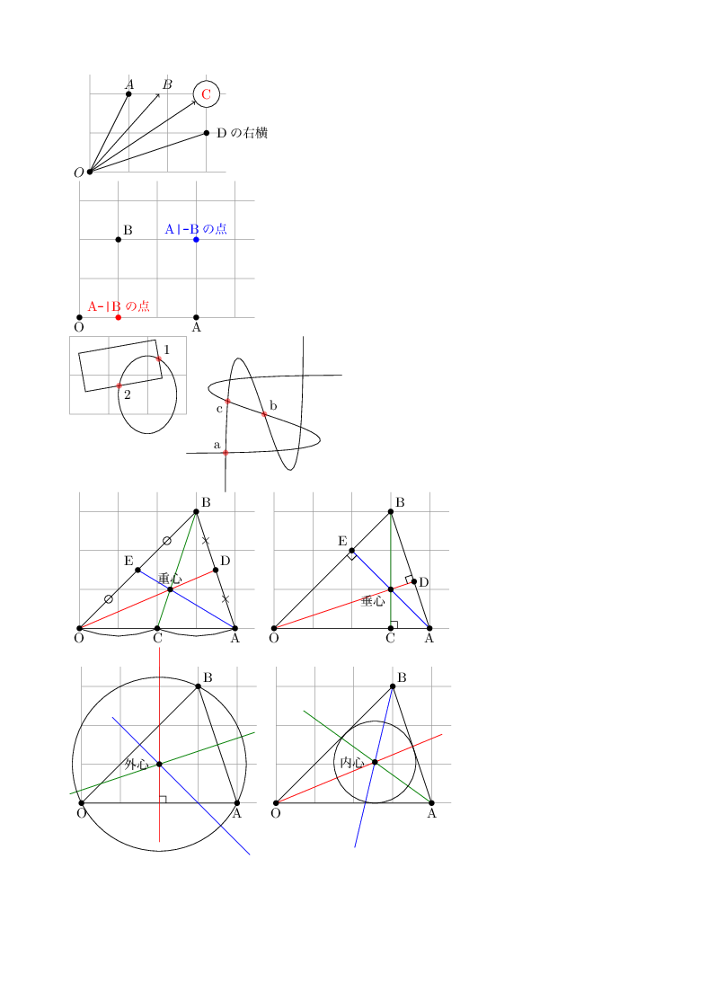
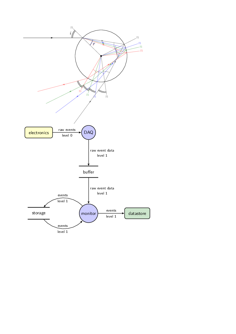
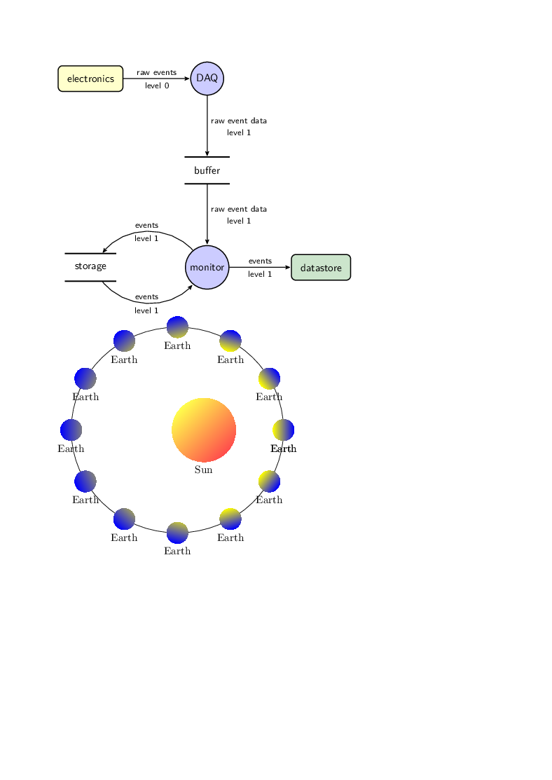
TeXソース
TeXソース
入力コード
\documentclass[b5j,10pt,twoside]{tetsujsarticle}
\usepackage{tetsuryoku}
\pagestyle{fancy}

\余白設定[
上余白=1truecm,
下余白=上余白,
左余白=1.414truecm,
左右差=0truecm,
段間隔=対称,
段組の仕切り線の太さ=.5truept,
ヘッダの縦幅=16truept,
ヘッダ下端と本文上端の縦間隔=10truept,
ヘッダと本文を仕切る線の太さ=0truept,
本文下端とフッタ下端の縦間隔=20truept,
本文とフッタを仕切る線の太さ=0truept,
傍注領域の幅=0truept,
本文端と傍注領域との間隔=0truept,
傍注同士の縦間隔=\baselineskip,
奇数ページの傍注位置=右,
偶数ページの傍注位置=左,
]


\makeatletter

\usepackage{tikz}


\usetikzlibrary{intersections,calc,arrows,decorations,decorations.markings,through,spy}

%\colorlet{examplefill}{yellow!80!black}

\makeatletter
\pgfdeclareshape{datastore}{
  \inheritsavedanchors[from=rectangle]
  \inheritanchorborder[from=rectangle]
  \inheritanchor[from=rectangle]{center}
  \inheritanchor[from=rectangle]{base}
  \inheritanchor[from=rectangle]{north}
  \inheritanchor[from=rectangle]{north east}
  \inheritanchor[from=rectangle]{east}
  \inheritanchor[from=rectangle]{south east}
  \inheritanchor[from=rectangle]{south}
  \inheritanchor[from=rectangle]{south west}
  \inheritanchor[from=rectangle]{west}
  \inheritanchor[from=rectangle]{north west}
  \backgroundpath{
    %  store lower right in xa/ya and upper right in xb/yb
    \southwest \pgf@xa=\pgf@x \pgf@ya=\pgf@y
    \northeast \pgf@xb=\pgf@x \pgf@yb=\pgf@y
    \pgfpathmoveto{\pgfpoint{\pgf@xa}{\pgf@ya}}
    \pgfpathlineto{\pgfpoint{\pgf@xb}{\pgf@ya}}
    \pgfpathmoveto{\pgfpoint{\pgf@xa}{\pgf@yb}}
    \pgfpathlineto{\pgfpoint{\pgf@xb}{\pgf@yb}}
 }
}
\makeatother


\begin{document}


\begin{tikzpicture}
\draw [help lines] (0,0) grid (3.5,2.5);%(0,0)から(3.5,2.5)までの"細線の方眼"
\coordinate (O) at (0,0) node at (O) [left] {$O$}; %(0,0)に点Oを設定し、その左に$O$と記載する
\coordinate (A) at (1,2); %(1,2)に点Aを設定する
\node (B) at (2,2) [above] {$B$} ; %(2,2) の上方にノードBを設定し、$B$と記載する
\node (C) [fill=white, draw, text=red, circle] at (3,2) {C}; %(2,2)に白塗りした円形のノードCを設定する

\coordinate (D) at (3,1) node at (D) [label=right:Dの右横] {};
	%(D)には「大きさ」がなく、その位置に無名のノードが置かれ、右にラベルがある
%\node (D) at (3,1) [label=right:Dの右横] {};
	%(D)には「大きさ」をもった無名のノードがおかれ、その右にラベルがある
\fill (O) circle (2pt) (A) circle (2pt) (D) circle (2pt); %点O,A, Dに黒丸をつける(1つの\fillで複数の点を対象にできる)

\draw (O) -- (A) node [above] {$A$}; %線分OAを描き、その上方にノードを設定して$A$と記載する(ノード自体は無名)
\draw [->] (O)--(B); %矢印OBを描く(Bが(2,2)の上方にあること、ノードBに大きさがあることに注目)
\draw [->] (O)--(C); %矢印OCを描く(矢印はノードCの輪郭まで)
\draw (O)--(D);%(D)の設定を\coordinateでしたか\nodeでしているかで線の長さが異なる
\end{tikzpicture}


\begin{tikzpicture}
\draw [help lines] (0,0) grid (4.5,3.5);%(0,0)から(4.5,3.5)までの"細線の方眼"
\coordinate (O) at (0,0) node [below] at (O) {O};
\coordinate (A) at (3,0) node [below]at (A) {A};
\coordinate (B) at (1,2) node [above right] at (B) {B};
\fill [red] (A -| B) circle (2pt) node [above] {A{\verb\-|\}Bの点};
\fill [blue] (A |- B) circle (2pt) node [above] {A{\verb\|-\}Bの点};
\fill (O) circle (2pt);
\fill (A) circle (2pt);
\fill (B) circle (2pt);
\end{tikzpicture}

\begin{tikzpicture}[every node/.style={opacity=1, black}]
%1つ目の図

\begin{scope}
\draw [help lines] grid (3,2);
\draw [name path=rectangle, rotate=10] (0.5,0.5) rectangle +(2,1);
\draw [name path=ellipse] (2,0.5) ellipse (0.75cm and 1cm);
\fill [red, opacity=0.5, name intersections={of=rectangle and ellipse}]
(intersection-1) circle (2pt) node [above right] {1} %第1の交点
(intersection-2) circle (2pt) node [below right] {2};%第2の交点
\end{scope}
%ここから2つ目の図

\begin{scope}[xshift=5cm]
\clip (-2,-2) rectangle (2,2);
\draw [name path=curve 1] (-2,-1) .. controls (8, -1) and (-8, 1) .. (2,1);
\draw [name path=curve 2] (-1,-2) .. controls (-1,8) and (1, -8) .. (1,2);
\fill [red, opacity=0.5, name intersections={of= curve 1 and curve 2, by={a, b, c}}]
(a) circle (2pt) node [above left] at (a) {a}
(b) circle (2pt) node [above right] at (b) {b}
(c) circle (2pt) node [below left] at (c) {c};
\end{scope}
\end{tikzpicture}


\begin{tikzpicture}
\begin{scope}%△OABの重心を求める
\draw [help lines] (0,0) grid (4.5,3.5);%(0,0)から(4.5,3.5)までの"細線の方眼"
%△OABの頂点を設定
\coordinate (O) at (0,0) node [below] at (O) {O};
\coordinate (A) at (4,0) node [below]at (A) {A};
\coordinate (B) at (3,3) node [above right] at (B) {B};
%各辺の中点を計算
\coordinate (C) at ($(O)!.5!(A)$) node at (C) [below]  {C};%OAの中点
\coordinate (D) at ($(A)!.5!(B)$) node at (D) [above right]  {D};%ABの中点
\coordinate (E) at ($(B)!.5!(O)$) node at (E) [above left]  {E};%BOの中点
%中点であることを示す
\node [circle, draw, inner sep=2pt] at ($(O)!.5!(E)$) {};
\node [circle, draw, inner sep=2pt] at ($(B)!.5!(E)$) {};
\node at ($(A)!.5!(D)$) {×};
\node at ($(B)!.5!(D)$) {×};
\draw (O) to [out=-20, in=200] (C);
\draw (C) to [out=-20, in=200] (A);
%線分を引く
\draw (O)--(A)--(B)--cycle;
\draw [red] (O)--(D) [name path=line 1];
\draw [blue] (A)--(E) [name path=line 2];
\draw [green] (B)--(C);
%各点に黒丸をつける
\fill (O) circle (2pt);
\fill (A) circle (2pt);
\fill (B) circle (2pt);
\fill (C) circle (2pt);
\fill (D) circle (2pt);
\fill (E) circle (2pt);
\fill [name intersections={of=line 1 and line 2}] (intersection-1) circle (2pt) node [above] {重心};
\end{scope}
%
\begin{scope}[xshift=5cm]%△OABの垂心を求める
\draw [help lines] (0,0) grid (4.5,3.5);%(0,0)から(4.5,3.5)までの"細線の方眼"
%三角形の頂点を設定
\coordinate (O) at (0,0) node [below] at (O) {O};
\coordinate (A) at (4,0) node [below] at (A) {A};
\coordinate (B) at (3,3) node [above right] at (B) {B};
%各頂点からの垂線の足を計算
\coordinate (C) at ($(O)!(B)!(A)$) node at (C) [below] {C};%BからOAに下ろした垂線の足
\coordinate (D) at ($(A)!(O)!(B)$) node at (D) [right] {D};%OからABに下ろした垂線の足
\coordinate (E) at ($(O)!(A)!(B)$) node at (E) [above left] {E};%AからOBに下ろした垂線の足
%線分を引く
\draw (O)--(A)--(B)--cycle;
\draw [red] (O)--(D);
\draw [name path=line 1, green] (B)--(C);
\draw [name path=line 2, blue] (A)--(E);
%C,D,Eに直角記号をつける
\draw ($(C)!5pt!(B)$) -| ($(C)!5pt!(A)$);
\draw ($(D)!5pt!(O)$)--($(D)!5pt!(O)!5pt!90:(D)$)--($(D)!5pt!(B)$);
\draw ($(E)!5pt!(A)$)--($(E)!5pt!(A)!5pt!90:(E)$)--($(E)!5pt!(O)$);
%各点に黒丸をつける
\foreach \P in {A,...,E,O} \fill (\P) circle (2pt);
\fill [name intersections={of=line 1 and line 2}] (intersection-1) circle (2pt) node [below left] {垂心};
\end{scope}
\end{tikzpicture}


\begin{tikzpicture}
\begin{scope}%△OABの外心を求める
\draw [help lines] (0,0) grid (4.5,3.5);%(0,0)から(4.5,3.5)までの"細線の方眼"
%三角形の頂点を設定し、三角形を描く
\coordinate (O) at (0,0) node [below] at (O) {O};
\coordinate (A) at (4,0) node [below] at (A) {A};
\coordinate (B) at (3,3) node [above right] at (B) {B};
\draw (O)--(A)--(B)--cycle;
%各辺の垂直二等分線およびその交点(=外心)
\draw ($(O)!.5!(A)!1cm!90:(O)$)--($(O)!.5!(A)!4cm!90:(A)$) [name path=line 1, red];
\draw ($(A)!.5!(B)!1cm!90:(A)$)--($(A)!.5!(B)!4cm!90:(B)$) [name path=line 2, green];
\draw ($(B)!.5!(O)!1cm!90:(B)$)--($(B)!.5!(O)!4cm!90:(O)$) [name path=line 3, blue];
\fill [name intersections={of=line 1 and line 2}] (intersection-1) circle (2pt) node (P) [label=left:外心] {};
\draw ($(O)!.5!(A)!5pt!(A)$) |- ($(O)!.5!(A)!5pt!90:(A)$);%直角記号
%各点に黒丸をつける
\foreach \P in {O,A,B} \fill (\P) circle (2pt);
%外心円(半径はOPの距離)
\node [draw, circle through=(O)] at (P) {};
\end{scope}
%
\begin{scope}[xshift=5cm]%△OABの内心を求める
\draw [help lines] (0,0) grid (4.5,3.5);%(0,0)から(4.5,3.5)までの"細線の方眼"
%三角形の頂点を設定し、三角形を描く
\coordinate (O) at (0,0) node [below] at (O) {O};
\coordinate (A) at (4,0) node [below] at (A) {A};
\coordinate (B) at (3,3) node [above right] at (B) {B};
\draw (O)--(A)--(B)--cycle;
%各辺上で一定の長さの点を設定する
\coordinate (s) at ($(O)!1cm!(A)$);
\coordinate (t) at ($(O)!1cm!(B)$);
\coordinate (u) at ($(A)!1cm!(O)$);
\coordinate (v) at ($(A)!1cm!(B)$);
\coordinate (w) at ($(B)!1cm!(O)$);
\coordinate (z) at ($(B)!1cm!(A)$);
%内角の二等分線
\draw (O)--($5*(s)!.5!(t)$) [name path=line O, red];
\draw (A)--($(u)!.5!(v)!-4!(A)$) [name path=line A, green];
\draw (B)--($(z)!.5!(w)!-4!(B)$) [name path=line B, blue];
%角の二等分線の交点(=内心)
\fill [name intersections={of=line O and line B}] (intersection-1) circle (2pt) node (P) [label=left:内心] {};
%各点に黒丸をつける
\foreach \P in {O,A,B} \fill (\P) circle (2pt);
%内心円(半径はPからOAに下ろした垂線の長さ)
\draw let \p1=($(O)!(P)!(A)-(P)$), \n1={veclen(\x1,\y1)} in circle [at=(P), radius=\n1];
\end{scope}
\end{tikzpicture}

% Draw an arc denoting an angle using start and delta angles
\newcommand{\drawarcdelta}[4]{
  \draw ($#1+(#2:#4)$) arc[start angle=#2, delta angle=#3, radius=#4];
}

% Draw an arc with label denoting an angle using start and delta angles
\newcommand{\drawlabeledarcdelta}[6]{
  \drawarcdelta{#1}{#2}{#3}{#4}
  \node at ($#1+(#2+#3/2:#6)$) {#5};
}


\begin{tikzpicture}[xscale=-1,
    ray/.style={decoration={markings,mark=at position .5 with {
      \arrow[>=latex]{>}}},postaction=decorate}
  ]

  % Radius of raindrop
  \pgfmathsetlengthmacro{\r}{2cm}
  % Position where the incoming ray enters the raindrop, as a fraction of
  % the height of the drop.  If 0., the ray will enter in the middle of the
  % drop, if 1., the ray will enter at the top of the drop.
  \pgfmathsetmacro{\f}{.7}

  % Various radii for drawing angle arcs and labels
  \pgfmathsetlengthmacro{\arcradius}{.8cm}
  \pgfmathsetlengthmacro{\dotradius}{.6cm}
  \pgfmathsetlengthmacro{\arclabelradius}{1cm}

  % Calculation of the angle of incidence
  \pgfmathsetmacro{\incidentangle}{asin(\f)}

  % Coordinates of origin and point of entry
  \coordinate (O) at (0, 0);
  \coordinate (A) at (\incidentangle:\r);

  % Draw the drop and the incoming ray, as well as the angle of incidence
  \draw (O) circle (\r);
  \draw[ray] (A  -| \r*3, 0) -- (A);
  \draw[gray] (O) -- ($(O)!1.5!(A)$) node[pos=1.05] {$n$};
  \drawarcdelta{(A)}{0}{\incidentangle}{\arcradius-1pt}
  \drawlabeledarcdelta{(A)}{0}{\incidentangle}{\arcradius+1pt}
    {$i$}{\arclabelradius}

  % For each red and blue ray.  The index of refraction for red light is
  % slightly exaggerated, it should be 1.33.
%  \foreach \index/\color in {1.2/black, 1.32/red, 1.45/green, 2.0/brown, 1.34/blue} {
  \foreach \index/\color in {1.2/black, 1.6/red, 1.45/green, 1.34/blue} {
    % Calculate angle of refraction
    \pgfmathsetmacro{\refractedangle}{asin(sin(\incidentangle) / \index)}
    % Calculate top angle (at O) in the triangle formed by O, the point of
    % entry, and the point of internal reflection
    \pgfmathsetmacro{\angleindrop}{180 - 2*\refractedangle}

    % Coordinate of point of reflection
    \coordinate (A') at (\incidentangle+\angleindrop:\r);
    % Coordinate of point of exit
    \coordinate (A'') at (\incidentangle+2*\angleindrop:\r);

    \begin{scope}[opacity=.5, color=\color]
      % Draw the light rays
      \draw[ray] (A) -- (A');
      \draw[ray] (A') -- (A'');
      \draw[ray] (A'') -- ($(A'')+(2*\incidentangle+2*\angleindrop:2*\r)$);

      % Draw the normal lines
      \draw (O) -- ($(O)!1.5!(A')$) node[pos=1.05] {$n$};
      \draw (O) -- ($(O)!1.5!(A'')$) node[pos=1.05] {$n$};

      % Draw the arcs and labels
      \drawlabeledarcdelta{(A)}{\incidentangle+180}{-\refractedangle}
        {\arcradius}{$r$}{\arclabelradius}
      \drawarcdelta{(A')}{\incidentangle+\angleindrop+180}{\refractedangle}
        {\arcradius}
      \drawarcdelta{(A')}{\incidentangle+\angleindrop+180}{-\refractedangle}
        {\arcradius}
      \drawarcdelta{(A'')}{\incidentangle+2*\angleindrop+180}{\refractedangle}
        {\arcradius}
    \end{scope}

    % Draw the arcs of the angles of the rays leaving the raindrop.  Note
    % that the angles are identical to the original angle of incidence.
    \drawarcdelta{(A'')}{\incidentangle+2*\angleindrop}{\incidentangle}
      {\arcradius-1pt}
    \drawarcdelta{(A'')}{\incidentangle+2*\angleindrop}{\incidentangle}
      {\arcradius+1pt}
  }

  % Mark the center of the raindrop
  \draw[fill] (O) circle (1.5pt);
\end{tikzpicture}

\begin{tikzpicture}[
  font=\sffamily,
  every matrix/.style={ampersand replacement=\&,column sep=2cm,row sep=2cm},
  source/.style={draw,thick,rounded corners,fill=yellow!20,inner sep=.3cm},
  process/.style={draw,thick,circle,fill=blue!20},
  sink/.style={source,fill=green!20},
  datastore/.style={draw,very thick,shape=datastore,inner sep=.3cm},
  dots/.style={gray,scale=2},
  to/.style={->,>=stealth',shorten >=1pt,semithick,font=\sffamily\footnotesize},
  every node/.style={align=center}]

  % Position the nodes using a matrix layout
  \matrix{
    \node[source] (hisparcbox) {electronics};
      \& \node[process] (daq) {DAQ}; \& \\

    \& \node[datastore] (buffer) {buffer}; \& \\

    \node[datastore] (storage) {storage};
      \& \node[process] (monitor) {monitor};
      \& \node[sink] (datastore) {datastore}; \\
  };

  % Draw the arrows between the nodes and label them.
  \draw[to] (hisparcbox) -- node[midway,above] {raw events}
      node[midway,below] {level 0} (daq);
  \draw[to] (daq) -- node[midway,right] {raw event data\\level 1} (buffer);
  \draw[to] (buffer) --
      node[midway,right] {raw event data\\level 1} (monitor);
  \draw[to] (monitor) to[bend right=50] node[midway,above] {events}
      node[midway,below] {level 1} (storage);
  \draw[to] (storage) to[bend right=50] node[midway,above] {events}
      node[midway,below] {level 1} (monitor);
  \draw[to] (monitor) -- node[midway,above] {events}
      node[midway,below] {level 1} (datastore);
\end{tikzpicture}


\begin{tikzpicture}[
  font=\sffamily,
  every matrix/.style={ampersand replacement=\&,column sep=2cm,row sep=2cm},
  source/.style={draw,thick,rounded corners,fill=yellow!20,inner sep=.3cm},
  process/.style={draw,thick,circle,fill=blue!20},
  sink/.style={source,fill=green!20},
  datastore/.style={draw,very thick,shape=datastore,inner sep=.3cm},
  dots/.style={gray,scale=2},
  to/.style={->,>=stealth',shorten >=1pt,semithick,font=\sffamily\footnotesize},
  every node/.style={align=center}]

  % Position the nodes using a matrix layout
  \matrix{
    \node[source] (hisparcbox) {electronics};
      \& \node[process] (daq) {DAQ}; \& \\

    \& \node[datastore] (buffer) {buffer}; \& \\

    \node[datastore] (storage) {storage};
      \& \node[process] (monitor) {monitor};
      \& \node[sink] (datastore) {datastore}; \\
  };

  % Draw the arrows between the nodes and label them.
  \draw[to] (hisparcbox) -- node[midway,above] {raw events}
      node[midway,below] {level 0} (daq);
  \draw[to] (daq) -- node[midway,right] {raw event data\\level 1} (buffer);
  \draw[to] (buffer) --
      node[midway,right] {raw event data\\level 1} (monitor);
  \draw[to] (monitor) to[bend right=50] node[midway,above] {events}
      node[midway,below] {level 1} (storage);
  \draw[to] (storage) to[bend right=50] node[midway,above] {events}
      node[midway,below] {level 1} (monitor);
  \draw[to] (monitor) -- node[midway,above] {events}
      node[midway,below] {level 1} (datastore);
\end{tikzpicture}


\begin{tikzpicture}[scale=3.5]
\pgfmathsetmacro{\Sunradius}{0.3}   % Sun radius
\pgfmathsetmacro{\Earthradius}{0.1} % Earth radius
\pgfmathsetmacro{\e}{0.25}          % Excentricity of the elliptical orbit
\pgfmathsetmacro{\b}{sqrt(1-\e*\e)} % Minor radius (major radius = 1)

% Draw the Sun at the right-hand-side focus
\shade[
  top color=yellow!70,
  bottom color=red!70,
  shading angle={45},
 ] ({sqrt(1-\b*\b)},0) circle (\Sunradius);
  \draw ({sqrt(1-\b*\b)},-\Sunradius) node[below] {Sun};

% Draw the elliptical path of the Earth.
\draw[thin] (0,0) ellipse (1 and {\b});

% This function computes the direction in which light hits the Earth.
\pgfmathdeclarefunction{f}{1}{%
  \pgfmathparse{
    ((-\e+cos(#1))<0) * ( 180 + atan( \b*sin(#1)/(-\e+cos(#1)) ) )
      +
    ((-\e+cos(#1))>=0) * ( atan( \b*sin(#1)/(-\e+cos(#1)) ) )
  }
}

% This function computes the distance between Earth and the Sun,
% which is used to calculate the varying radiation intensity on Earth.
\pgfmathdeclarefunction{d}{1}{%
  \pgfmathparse{ sqrt((-\e+cos(#1))*(-\e+cos(#1))+\b*sin(#1)*\b*sin(#1)) }
}

% Produces a series of frames showing one revolution
% (the total number of frames is controlled by macro \N)
\pgfmathtruncatemacro{\N}{12}
\foreach \k in {0,1,...,\N}{
  \pgfmathsetmacro{\theta}{360*\k/\N}
    \pgfmathsetmacro{\radiation}{100*(1-\e)/(d(\theta)*d(\theta))}
    \colorlet{Earthlight}{yellow!\radiation!blue}
    \pgfmathparse{int(\k+1)}
      % \onslide is used instead of \visible<.-(x)> and \pause,
      % in order not to break header and footer.
      \shade[
        top color=Earthlight,
        bottom color=blue,
        shading angle={90+f(\theta)},
      ] ({cos(\theta)},{\b*sin(\theta)}) circle (\Earthradius);
        \draw ({cos(\theta)},{\b*sin(\theta)-\Earthradius}) node[below] {Earth};
    }
\end{tikzpicture}

\end{document}